
What Is a SMARC Carrier Board? Architecture, Interfaces and How to Choose the Right One

Written By:Stephen Athokpam,Embedded Computing & Industrial Systems Specialist, Portwell India
Reviewed By: Portwell India Industrial Computing Team
Published On: 30 October 2026
Table of Contents
A SMARC module can provide an embedded system with its core computing functionality. A carrier board is used to interface with external devices, peripherals and other parts of the system.
Choosing the correct SMARC carrier board is a key part of creating a reliable solution.
In this article, we will talk about what a SMARC carrier board is, how the SMARC module interacts with the carrier board and what interfaces are available.
Key Takeaways
• A SMARC carrier board connects a SMARC module to external devices.
• The SMARC module contains the processor, memory, and main computing parts.
• A standard 314-pin connector links the SMARC module to the carrier board.
• The carrier board provides connections for displays, USB, Ethernet, storage, and other devices.
• Not all SMARC carrier boards support the same interfaces.
• Check module compatibility, power needs, cooling, and expansion options before choosing a carrier board.
• The right carrier board helps build a reliable embedded computing system.
What Is a SMARC Carrier Board?
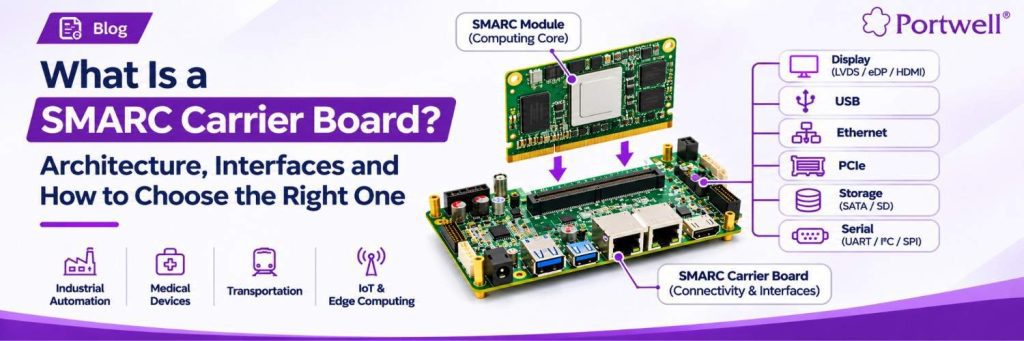
A SMARC carrier board is used as a baseboard to interface external components and interfaces with a SMARC (Smart Mobility Architecture) computer-on-module.
The SMARC module holds all of the core computing components such as the processor, memory and other crucial circuitry. The carrier board provides the connectors, power circuits and interfaces needed to integrate everything together into a complete embedded system.
In simple terms:
SMARC Module: Provides the processing functionality.
SMARC Carrier Board: Connects the module to external devices, power, displays, storage and communication interfaces.
How Does a SMARC Module Work with a Carrier Board?
An embedded system using a SMARC module usually consists of two main components.
The SMARC module is connected to the carrier board using a standard 314 pin connector. This allows the processor and other components on the module to interact with the interfaces on the carrier board.
The carrier board then sends the required signals to the external connectors based on the design of the system.
The basic architecture would be:
- SMARC Module: Processor, memory, core components.
- Connector: Electrical connection between the module and carrier board.
- Carrier Board: Sends power, data, and control signals to the correct interfaces.
- External Peripherals: Displays, storage, network connections, sensors, and other application-specific components.
This design makes it easier for the developer to choose a suitable computing module. As well as designing or choosing a carrier board that suits their application.
What are the Interfaces Available on a SMARC Carrier Board?
The interfaces available on a SMARC carrier board depend on its design, the SMARC module and the selected processor platform.
Common interface categories include:
1. Display Interfaces
Display interfaces allow the embedded system to connect with monitors, industrial displays and human-machine interface (HMI) panels.
Depending on the module and carrier board design, display connectivity may include:
- LVDS
- eDP
- HDMI or DisplayPort, where supported by the platform
These interfaces are useful in industrial HMI systems, medical equipment, digital signage and other display-based applications.
2. USB Interfaces
USB interfaces connect external peripherals such as cameras, keyboards, touchscreens, storage devices and other USB-enabled equipment.
The supported USB versions and number of ports depend on the module’s capabilities and carrier board implementation.
3. Ethernet Connectivity
Ethernet interfaces provide wired network connectivity for communication between embedded systems, industrial equipment, servers and other network devices.
They are commonly used in industrial automation, IoT gateways and network-connected embedded applications.
4. PCIe Expansion
PCI Express (PCIe) provides high-speed connectivity for compatible expansion devices.
Depending on the available lanes and board design, PCIe can support expansion cards, communication modules and other application-specific components.
5. Storage Interfaces
Storage interfaces allow the system to connect with supported storage devices.
Depending on the platform, these may include SATA, SD and other supported storage options. The actual availability should be checked against the module and carrier board specifications.
6. Serial and General-Purpose Interfaces
Serial interfaces and general-purpose input/output (GPIO) signals support communication with sensors, controllers and external equipment.
Common examples include UART, I²C, SPI and GPIO. These interfaces are particularly useful in industrial control, monitoring and automation applications.
SMARC Carrier Board vs SMARC Module: What Is the Difference?
Although the SMARC module and carrier board work together, they serve different purposes in an embedded computing system.
| Parameter | SMARC Module | SMARC Carrier Board |
|---|---|---|
| Parameter | SMARC Module | SMARC Carrier Board |
| Main purpose | Provides computing power | Provides connectivity and system integration |
| Components | Processor, memory and core circuitry | Connectors, power circuits and interface routing |
| Connectivity | Exposes signals through the module connector | Routes signals to external interfaces |
| Design focus | Computing performance and module capabilities | Application-specific connectivity and integration |
| Selection factors | Processor, memory, performance and power | Interfaces, connectors, power input and application requirements |
The module determines the core computing capabilities, while the carrier board determines how those capabilities are connected to the rest of the system.
How to Choose the Right SMARC Carrier Board
Choosing a SMARC carrier board requires more than checking the number of available connectors. It is important to understand the complete system requirements and confirm compatibility with the selected module.
Here are six factors to consider.
1. Check SMARC Standard and Module Compatibility
Start by checking whether the carrier board is designed for the SMARC module you plan to use.
Verify the connector, mechanical dimensions, pinout and supported signals. Also check the applicable SMARC specification and module documentation.
A standardized connector does not automatically mean every module and carrier board combination will support every feature.
2. Identify the Required Interfaces
List the interfaces required by your application before selecting a carrier board.
For example:
- Industrial HMI systems may require display, USB and Ethernet connectivity.
- IoT gateways may require Ethernet, serial communication and expansion options.
- Industrial automation systems may require GPIO, UART and other control interfaces.
Select a carrier board that supports the required signals and connectors without adding unnecessary complexity.
3. Evaluate Power Requirements
Power requirements should be checked at both module and system levels.
Consider the input voltage, power consumption, power sequencing and the requirements of connected peripherals. The carrier board’s power design must be compatible with the selected module and the complete system.
4. Consider Thermal Management
Thermal performance is important, particularly in industrial environments where systems may operate continuously or experience changing ambient temperatures.
Check the module’s thermal requirements, cooling arrangement, heatsink compatibility and airflow conditions. The carrier board and enclosure design should support the intended operating environment.
5. Check Expansion and Future Requirements
Consider whether the application may require additional connectivity or expansion in the future.
Review available PCIe lanes, USB ports, storage options, serial interfaces and other expansion capabilities. Choosing a suitable configuration at the beginning can reduce redesign requirements later.
6. Review Documentation and Technical Support
Technical documentation is important during system integration and product development.
Before selecting a platform, review:
- Module datasheets
- Carrier board specifications
- Connector and pinout documentation
- Supported operating systems
- Power and thermal guidelines
- Design and integration support
Access to clear technical documentation can help developers reduce integration challenges.
Where Are SMARC Carrier Boards Used?
SMARC carrier boards are used in embedded systems that require compact computing, flexible connectivity and application-specific integration.
Common application areas include:
Industrial Automation
SMARC-based systems can be used in industrial control equipment, machine interfaces, monitoring systems and factory automation platforms.
Medical Equipment
Embedded computing platforms can support medical devices and diagnostic equipment that require compact computing and suitable peripheral connectivity. The final design must meet the applicable medical-device requirements.
Transportation Systems
SMARC-based platforms can be integrated into transportation equipment, onboard computing systems and monitoring applications, depending on environmental and regulatory requirements.
IoT Gateways and Edge Computing
SMARC modules combined with suitable carrier boards can support connected devices, data collection, network communication and edge computing applications.
Retail and Digital Signage
Display, network and peripheral connectivity make SMARC-based platforms suitable for selected retail automation, interactive display and digital signage systems.
What are the common mistakes to avoid when selecting a SMARC Carrier Board?
A carrier board may appear suitable based on its connector layout, but overlooking technical requirements can create integration problems.
Watch out for these common mistakes:
- Selecting a carrier board without checking the module pinout.
- Assuming all SMARC modules support the same interfaces.
- Ignoring power sequencing and peripheral power requirements.
- Overlooking thermal management and enclosure limitations.
- Choosing a board without considering future expansion.
- Not checking operating system and driver compatibility.
- Relying only on connector availability without verifying actual signal support.
Reviewing the module and carrier board documentation together can help avoid these issues.
Frequently Asked Questions About SMARC Carrier Boards
A SMARC carrier board connects a SMARC computer-on-module to external devices and system components. It provides power circuits, connectors and interface routing for displays, storage, networking and peripherals.
No. A SMARC module contains the processor, memory and core computing components. A carrier board provides the connectivity and interfaces needed to integrate the module into a complete embedded system.
The SMARC module uses a standardized 314-pin connector to connect with the carrier board.
It may support multiple compatible modules, but compatibility must be verified. Check the connector, pinout, power requirements, signal availability and module specifications before combining them.
Depending on the module and carrier board design, interfaces may include USB, Ethernet, PCIe, display interfaces, SATA, SD, UART, I²C, SPI and GPIO.
Start with the required processor platform and application interfaces. Then verify module compatibility, power requirements, thermal design, expansion options, operating conditions and technical documentation.
No. Interface availability depends on the SMARC module, processor platform, pin configuration and carrier board design. Always check the technical specifications before selecting a board.
References
For further technical information about SMARC modules and carrier board design, refer to the following resources:
Looking for SMARC-based embedded computing solutions?
Get A Free Demo
Stephen Athokpam
Stephen Athokpam is an Embedded Computing Systems Specialist at Portwell, covering COM Express modules, industrial motherboards, and edge AI systems for OEMs and system integrators.